Silvercrest/SME can design and build Motor-pump sets, ROV HPU, SUBSEA, SUBMERSIBLE, ROV motors to suit any requirement
due our totally flexible design capabilities:
SILVERCREST / SME.
Tel: (+44) 1285.760620.
Email: sales@SilvercrestSubmarines.com
 Flexible External Dimensions to suit
all applications. Flexible External Dimensions to suit
all applications.
Dimensions to allow drop in
replacement for existing units.
Anodised aluminium, or, 316
stainless steel.
Power drive to load using an output
shaft with a standard coupling, or, close coupled, etc.
Single drive shaft, or, a drive
shaft at both ends, (double shaft extension).
SME can design and
build a motor with a completely new lamination to meet special
design requirements, if necessary.
SME design their motors so they do not run hot. Typical motors
can run on deck for at least 10 minutes on full load, with no
cooling, without overheating. The motors are designed to be compact
in size and suitable for heavy duty applications, like trenching.
If weight is important SME can design the motor for minimum weight
by utilising an aluminium construction and a hollow motor shaft,
etc., while still ensuring the motor is generously rated for full
load operation. If the motor is going to drive a hydraulic pump we
recommend a close coupled arrangement to save the weight of the
coupling and the coupling housing.
SME can design and build motors for all voltages from 24 Volts to
4160 Volts with 50Hz or 60Hz frequencies, or for VVVF requirements.
High Voltage motors can have random stator windings, or formed
coils, depending on space and weight constraints. The winding wire
for the High Voltage motors is double insulated and passes a twisted
wire test at 16,000 volts and is rated up to 155 Deg.C. All windings
are designed to keep 'turn to turn' voltage to a minimum. All
winding materials and cables, etc. are specially selected to be
suitable for use in hydraulic oil.
In general the SME SUBSEA motors have low loss lamination steel (3
Watts/kg), which allows for higher flux densities, and less heat,
with less material and weight.
All motors are oil filled and we recommend hydraulic oils for good
lubrication characteristics in preference to electrical oil which
has better di-electric capabilities, but worse lubrication
capabilities.
If motors are going to drive a water pump SME can design the motor
to take the thrust load from the pump, and keep the sea water out of
the motor with a single or double mechanical seal arrangement.
Thruster motors can be designed and built for voltage/speed control,
which is a relatively simple speed control system, and they can also
be built with a thrust bearing incorporated to take the thrust load
from the impeller.
To ensure the integrity of the motor housing SME does not use
castings. All components are machined from solid or from extrusions.
The external aluminium components are typically 6061 T6 marine grade
aluminium and hard anodised to a military specification.
All ball bearings are from well known brands such as SKF, FAG, or
NSK. Oil seals are high temperature and typically made from Viton.
Mechanical seals are typically Burgmann.
All hardware used on SME SUBSEA motors is 316SS.
All fixing holes are blind except the "oil in" and "oil out"
fittings and the stator pack fixing bolt, if applicable.
The preferred power cable entry system for SME motors is to use an
"oily tube" connected to an adaptor which is part of an oil tight
rubber gland which is fixed to the stator frame. SME do not
recommend bringing the power cables through the endshields of the
motor because this creates additional complications when the motors
are stripped down during service, because the endshields cannot be
readily removed from the stator. Subsea connectors can be offered as
an alternative to the Oily Tube if requested.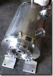
SME strongly recommend that the motors are supplied with PT100s
fitted in the windings and also in the bearings and that the
internal motor temperatures are monitored and set up to alarm if the
temperatures rise above the "norm". SME can also offer additional
protection with a water detector, etc. The auxiliary connections for
PT100s, etc. can be made through standard high pressure, water
tight, plug and sockets as supplied by "Subconn", "Impulse", and
"Burton". These are also fitted to a connection block on the stator,
not on the endshield.
All finished motors are pressure tested to ensure they are "oil
tight" and suitable for compensated operation down to 4000 metres.
All motors are rated for continuous operation and all prototype
motors are full load performance tested at rated voltage and rated
frequency to confirm their performance characteristics. All motors
can be issued with a "Type Test Certificate" or even full load
tested at additional cost, if required.
SME can also offer to arrange for hydraulic pumps to be set up and
tested on the motors at rated voltage and frequency.
SME can offer to supply Hydraulic Power Units, ROV HPU, complete with the
addition of a customer specified Hydraulic Pump. Also motor-pump sets for both hydraulic and water jetting applications.
SME is a fully quality assured company to ISO 9001.2000 for "Design,
development, manufacture, and testing of submersible electric motors
and electric motors for remotely operated vehicles".
SME Subsea motors can be designed and built for all subsea
applications, such as ROVs, Trenchers, Ploughs, Submarines, Dredges,
etc.
All makes of subsea motor can be serviced, repaired and tested by
SME. In some cases the original motors can be significantly
upgraded. If you are having problems with your existing subsea
motors please contact SME - we are keen to help and we are very
price competitive.
At SME we are continually working on improving the performance of
our products and for this reason we reserve the right to make
changes without notice to any of the data in this brochure.
SUBSEA/ROV MOTORS:
Silvercrest/SME build and repair ROV submersible motors for all subsea applications. We design, manufacture, and supply, submersible electric motors for all SUBSEA and ROV, SUBSEA equipment, also for any special purpose submersible electric motor requirements.
Silvercrest/SME offer SUBSEA electric generators for Tidal Power Generation.
We repair and rewind large high voltage (500kW, 6600V) submersible electric motors.
High Temperature Submersibles in 6-inch to 20inch frames suitable for operation in ambient temperatures of 75 Deg. C.

Supply High Voltage water filled submersible motors (3300V, 4160V and 6600V)

Supply Upgraded Temperature Monitoring units, with new improved user-friendly parameter settings.

Manufacture Subsea and ROV motors suitable for depths of 4000M.

Manufacture Subsea Electric Generators for Tidal Generation.
Induction Generators or slow speed Permanent Magnet Synchronous Generators unto 500kW.
SUBMERSIBLE MOTORS and PUMPS.
We offer a wide range of electric submersible motors with matched hydraulic and water pumps.
We have our own submersible motors that are drop-in replacements for most of the popular models in use today.
We can supply ROV HPU submersible motors from 30kW to 250kW, trenching HPU submersible motors from 100kW to 500kW, trenching jetting pumps, plough HPU submersible motors, plough jetting pump sets, turbine and centrifugal water pumps, and hydraulic pumps (Rexroth A7 and A10 series, Sauer 90 series and Kawasaki KV3 series).
We offer AC thrusters as direct replacements to existing DC thrusters from 1kW to 50kW in size.
Silvercrest/SME design and build specialized Submersible ROV motors for use SUBSEA in the offshore industry. These motors are usually made to order and vary from 1kW to 600kW, from 400 to 6600 Volts, 50 or 60 Hz, 2 Pole, 4 Pole, 6 Pole and 8 Pole.
We can repair, rewind, rebuild, and redesign any ROV submersible electric motor.
Silvercrest/SME design and manufacture specialized motors for use on SUBSEA equipment used in the offshore industry.
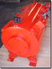
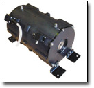
There are two common methods of construction - stainless steel construction or Marine Grade aluminium that is Black anodized to resist corrosion. We can also offer motors manufactured from Duplex and Super Duplex stainless steel.
Our subsea motors are usually oil filled and pressure compensated. The common operating voltages are 400 volts, 3300 volts, 4160 volts and 6600 volts (even for small 5kW motors). Our motors operate at depths down to 4000 metres, or deeper by special request.
Silvercrest/SME manufacture complete submersible electric motors, motor-pump sets, and ROV HPU.
We offer submersible motor rewinding / rebuilding /electrical conversion / and original construction modification.
SME can repair and completely rebuild most submersible electric motors (for example: Alstra, Aturia, Bamsa, B. J., Elmaksan, Exodyne/EEMI, G.E., Hayward Tyler, Hitachi, Mercury, Oddesse, Pleuger, Saer, S.M.E., Subteck, Sumo, Sun Star, U.S.).
Company Profile.
Silvercrest/SME manufactures new Submersible and ROV Motors. SME also services and repairs all brands of Submersible and ROV Motors. Including Hitachi, Pleuger, Grundfos, Mercury, Byron Jackson, Haywood Tyler, and Franklin. Our business is to manufacture, supply and service Submersible Electric Motors, Subsea and ROV motors. With a compliment of 30 service orientated staff members, we have the ability to service and technically support all makes and models of Submersible Electric Motors at our Maddington, Perth facility. Our sales department, with a total of 75 years experience in the Submersible and Electric motor business, are happy to assist with any enquiries on the purchase of Submersible Motors, HPU, and motor-pump sets, ranging from 3.7kw to 1500kw, in various voltages and frequencies.
In our 1200 ft facility, purpose built for manufacture and service of Submersible Electric Motors we offer the following in-house services:
Full Machine Shop capacity.
Voltage Testing through 10,000 volts.
ISO9001 quality assured workshop.
An Overhead crane through 10 ton capacity.
A state of the art Water Pressure Test facility with full international certification.
High POT and Surge Testing.
Full Load / Dyno testing to 250kw of all types of Electric Motors with detailed test reports.
Balancing Facility available, to 250 kg.
SME are a fully integrated manufacturing facility and in addition to our Standard range of submersible motors we also offer the following:
Special Motors for specialist applications.
4 Pole, 6 Pole and 8 Pole motors.
All Stainless Steel or more exotic material construction.
Special Thrust ratings.
Special Lead manufacturing.
NEMA and other couplings in a variety of materials.
Replacement parts of obsolete products.
Technical assistance during Commissioning.
Trouble Shooting.
Repairs to all makes (Oil and Water filled).
Rewinds of all Voltages (200 volt to 6.6kv) with 1 Year Warranty on all rewinds.
Dynamic testing.
Non-Destructive testing.
Welding and Machining.
On site or Factory Based Cable Splicing.
Retro Fitting of Condition Monitoring Equipment.
Modification of existing motors to upgrade them higher specifications.
Refurbishment of ROV motors using more technically advanced materials.
Please
contact us direct for confirmation of any drawing dimensions or
performance data.
To Contact us:
Silvercrest/SME.
Tel: (+44) 1285.760620
Email: sales@SilvercrestSubmarines.com
SUBMERSIBLE MOTORS, ROV MOTORS, SUBSEA MOTORS for Sale.
MOTOR-PUMP SETS, ROV HPU for Sale.
TIDAL ELECTRIC GENERATORS.
Silvercrest/SME specialize in the bespoke manufacturing of submersible motors, Rov motors, and subsea motors, motor-pump sets, and HPU's for use on Rovs, subsea trenchers, subsea ploughs, dredgers and water lift pump systems. For use in the offshore Oil and Gas and Telecommunications industries, and subsea to depths of 4000m.
We offer a range of motors, motor-pump sets, ROV HPU, submersible, subsea and Rov motors (5hp to 1500hp) for use in the more popular classes of subsea ploughs and Rovs.
All of these motors are available in either SS316, Duplex, Super Duplex stainless steel, or with a hard anodized aluminium finish.
We can offer subsea submersible motors with a wide range of speeds and voltages (including 3000v, 6000v and 10,000v).
Silvercrest/SME will design and build motors to suit your individual and special project requirements.
We refurbish and service a wide range of submersible motors.
Our product is excellent, our prices very competitive, and our delivery schedule the best in the industry.
Submersible Motor Engineering/Silvercrest is the world leader in submersible motor technology, enabling our customers to explore deeper underwater than ever before.
High power, high voltage and high-pressure specifications are common place for many of our clients.
Our submersible subsea and ROV motors are the best on the market today, offering a comprehensive choice of materials and design to underwater and ROV operators.
Submersible Motor Engineering/Silvercrest specializes in all aspects of submersible electric motor operation, performance, and design.
Due to industry demand for readily available quality parts, we also rewind, repair, redesign, and machine major components of other manufacturer's motors that require repair and re-manufacture.
We recently delivered ten 260kW, 3000VAC, double ended, 2 pole, stainless steel bodied motors to CTC Marine Projects Ltd, for use on their fleet of sub-sea trenchers. This was a bespoke order that was completed in just six weeks from receipt of order.
Also five 400kw, 4 –Pole, 3300/3/60, SS316 Construction, Subsea Submersible Motors for SMD.
Silvercrest/SME supply submersible motors, HPU's, and motor-pump sets worldwide. Our customers include SMD, Saab SeaEye, Ldtravocean, Fugro, CTC Marine Projects, Perry Slingsby and many others.
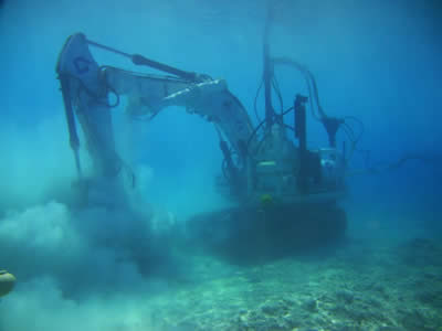
Subsea Trencher fitted with our SME 142-265KW stainless steel construction submersible motor and pump.
Silvercrest/SME have manufactured and recently supplied six 400kw ROV20-4 motors, 4-pole/3300vac/3 phase/60hz, stainless steel construction. Single ended for fitment with Sauer hydraulic pumps Series-90-L250. Rated for 3000m depth operations.
Also three ROV204 submersible motors (300kw/4 pole/3300vac/3 phase/60hz) with stainless steel construction, and double ended for fitment with Sauer hydraulic pumps to SMD-Hydrovision. Together with 7.5kw motors for Rov cursor application.
Silvercrest/SME has manufactured a seven (7) 6600V motors, for three different offshore contracts. Petronas Dulang and Angsi Platforms. Star Energy KG Platform.
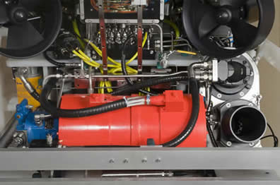
A new Saab-SeaEye Jaguar ROV, fitted with our SME ROV12-2, 48kW 65HP, 2-pole, 3000/3/50, aluminium construction ROV submersible motor, and Rexroth hydraulic pump. Fitted with temperature sensing and water detectors. Epoxy coated for protection.
Two submersible double-ended motors mounted with hydraulic pumps, fitted to a submarine digger. SME ROV14-4, 75kW/100HP, 4–pole, 3000/3/60, Anodised Aluminium Subsea Motors with Interface to suit the Hydraulic Pumps.
We manufacture and rebuild very large submersible motors for a range of different offshore and subsea companies. These include: Global Marine, CTC, Sonsub, Star Energy, Sulzer Wood, Sulzer, Fugro, Apache, BHP Billiton, Petronas, SMD, Exxon Mobile, Chevron, Perry Slingsby, Subsea7, Bayu Purnama, ISE Ltd, Saudi Aramco, Woodside, PXP.
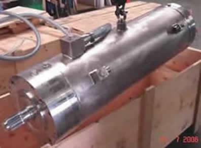
260kW Silvercrest/SME Pump Motor under construction.
Silvercrest/SME will bespoke manufacture virtually any shape and size of submersible motor required for subsea operations. We will be very happy to discuss the details of your subsea motor / pump requirements in order to produce a detailed technical quote for you.
Silvercrest/SME design and build specialized subsea motors, and support packages for use on all types of Rovs and underwater vehicles in the offshore and subsea industry. These submersible motors are usually made to order and vary from 1kW to 1500kW, 400 to 6600 Volts. 50 or 60 Hz, 2-Pole to 8-Pole.
There are two common methods of construction available: - Stainless steel construction, or Marine Grade aluminium that is Black anodised to resist corrosion. In addition we can offer Duplex and Super Duplex stainless steel construction.
These motors are usually oil filled and pressure compensated.
Common operating voltages are between 300 volts and 3300 volts - even for small 5kW motors. 6,000vac and 11,000vac motors also available by special request.
Certain subsea motors can operate down to depths of 10,000 meters.
Silvercrest/SME manufactures new Submersible, Subsea, and Rov motors.
Silvercrest/SME rewinds, services and repairs all brands of Subsea, Submersible and Rov motors. Including Hitachi, Pleuger, Grundfos, Mercury, Byron Jackson, Haywood Tyler, and Franklin.
Silvercrest/SME is a leading manufacturer of high quality submersible motors and pumps, designed specifically for subsea operations.
Silvercrest/SME specialize in the bespoke manufacturing of submersible motors, pumps and ancillary equipment for use on Rovs, subsea trenchers, subsea ploughs, dredgers and water lift pump systems, for use in the offshore Oil and Gas and Telecommunications industries.
We manufacture our own laminations, designed specifically to meet the individual requirements of each customer. We do not buy off the shelf standard rotor sets and fit them in a housing, as some other manufacturers will often do. As a result our motors are more efficient and generally ightly smaller, in both diameter and length, than our nearest competitors for any given power rating.
Silvercrest/SME offer a range of ‘standard’ motors for use in well-established underwater installations, such as the more popular classes of Rov and subsea ploughs.
SILVERCREST/SME offer:
Repair and rewind of large high voltage (500kW, 6600V) submersible electric subsea motors.
High Temperature Submersible subsea motors in 6-inch to 20-inch frames suitable for operation in ambient temperatures of 75 Degrees C.
High Voltage water filled submersible subsea motors (3300V, 4160V and 6600V).
Upgraded Temperature Monitoring units available with new improved user-friendly parameter setting.
ROV and subsea submersible motors suitable for depths of 4000m (10,000m depths by request).
WD Series sump-pump motors.
Subsea Electric Generators for Tidal Generation.
Induction Generators or slow speed Permanent Magnet Synchronous Generators up to 500k.
CONTACT US TODAY TO DISCUSS YOUR SUBSEA and ROV MOTOR REQUIREMENTS.
Tel: (+44) 1285.760620
Email: sales@SilvercrestSubmarines.com
Heat Exchanger Motors.
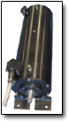
We now offer a complete range of water filled, watertight, submersible subsea motors with integral heat exchangers in 10-inch, 12-inch, 14-inch and 16-inch size for 2 pole and 4 pole speeds.
These subsea motors offer a significantly lower temperature rise when compared with standard submersible subsea motors. This is an advantage that can be utilized when customers want to operate in water with a high ambient temperature, or when there will be minimal cooling water flow available. Even with the standard applications the lower temperature rise will extend the life of the motor significantly. There is an accepted rule of thumb for electrical insulation that its life is shortened by one-half for every 10°C increase in operating temperature. The winding operating temperature for a normal water filled submersible motor is about 70 degrees.C, in 25 degree.C water. However an SME Heat Exchanger Motor will be running at about 45 degree.C. (This is 25 degrees cooler). This magnitude of difference in temperature rise will have a significant positive impact on motor life.
The basic design principle for these subsea motors is to circulate the internal water in the motor remove the heat from the "active" parts of the motor, and then pass it through a heat exchanger which brings the internal water back to somewhere close to the external ambient water temperature - before feeding it back through the "active" parts again to remove more heat. The heat exchanger increases the external surface area of the motor by 50% and the water circulation allows the heat to dissipate more evenly and quickly out of the subsea motor and into the external water. The small impeller inside the subsea motor that circulates the water has an insignificant impact on the motor efficiency in terms of additional load, while the subsea motor has an improved efficiency because the stator and rotor copper losses are reduced due to the lower operating temperature.
Motor Thermal Protection Unit
All SME Heat Exchanger Motors come with four (4) PT100 temperature sensors installed in the motor.
One PT100 is attached to the thrust bearing assembly that will detect excessive thrust loads
and overheating in the thrust bearing.
One PT100 is installed in the end winding on the non-drive end of the motor.
One is installed half way down the slot in the winding in the middle of the motor.
One is installed in the end winding on the drive end of the motor.
SME can offer one temperature protection unit (SME4TM) to monitor all four PT100'S installed in the Heat Exchanger Motor.
Water Pump Motors.
Our water pump motors are not vertically oriented, water filled, down hole pump motors, as has previously been the norm throughout the subsea industry. Silvercrest/SME motors are substantial oil filled submersible motors, designed to run in the horizontal axis with a large thrust bearing assembly to withstand water pump loads.
We can offer specially designed turbine pumps to match our motors. Again these pumps are not the usual vertically oriented type, these are specifically designed with a twin bearing arrangement, for use in the horizontal axis. Thus dramatically extending operational life and improving pump reliability.
Silvercrest recently delivered ten 260kW, 3000VAC, double ended, 2 pole, stainless steel bodied motors to CTC Marine Projects Ltd. The motors will be used by CTC on their subsea plough and trenching vehicles worldwide. This was a bespoke order that was completed in six weeks from receipt of order, ex-works from our manufacturing facility in Australia.
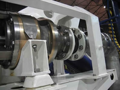
The 260kW/ 3000V / 60Hz / 2 pole pump motors (designed specifically for use in the horizontal axis) were fitted with shafts at both ends, in order to mate with three tandem mounted hydraulic pumps on one end and a Hayward Tyler M6 single stage water pump-set on the opposite end. In this 260kW model, rather than using the pivot shoe arrangement, typical of vertically oriented pump-sets, heavy duty tapered roller bearings were fitted to the rotor to manage the water pump induced end-loads. Thus giving a calculated bearing life in excess of 11,000 hours, even when used in the horizontal axis. Depth rating on each motor is 10,000 meters, with oil filled compensation. Motor housings are 316 stainless steel, with Mylar coated windings (the ultimate in winding coating technology) being used in each motor at the request of CTC, giving an insulation rating of >16kV at a temperature of 140 degrees C.
Rov and Subsea Plough and Trencher Motors.
Silvercrest offer an established range of Rov motors ranging from 5HP to 500HP. All of these motors are available in either SS316 or Hard Anodized Aluminium finish. We will also design and build submersible motors to suit your individual requirements and subsea project.
Our motors are in use with most of the major operators worldwide such as Saipem, SMD Hydrovision, Sonsub, CTC Marine Projects, Impresub, Fugro, Thales, MTQ, LD Travocean and Canyon Offshore.
265KW Trencher Motor.
Submersible ROV HPU and Compensation Units.
Silvercrest/SME manufacture and supply a wide range of electric submersible motors, motor-pump sets, together with matched hydraulic pumps (HPU) or water pumps.
We can supply ROV HPU submersible motors from 30kW to 250kW, trenching HPU submersible motors from 100kW to 450kW, trenching jetting pumps, plough HPU submersible motors, plough jetting motor pump sets, turbine and centrifugal water pumps, hydraulic pumps, Rexroth A7 and A10 series pumps, and Sauer 90 series & Kawasaki KV3 series pumps.
We also offer a range of subsea components for manned submersibles, ROVs, submarines, subsea trenchers and subsea ploughs.
Also oil compensation units (Compensators). We supply AC thrusters as direct replacements to existing DC thrusters from 1kW to 50kW in size.
Oil Compensator Units.
Silvercrest/SME supply oil compensator units for subsea vehicles, to suit manned submersibles, ROVs, submarines, subsea trenchers and subsea ploughs, and subsea equipment.
We can offer a range of oil compensation unit sizes, including a 2.7L Compensator. 7 x 1/4" NPT (BSPT). SA-HC-0745-MAS.
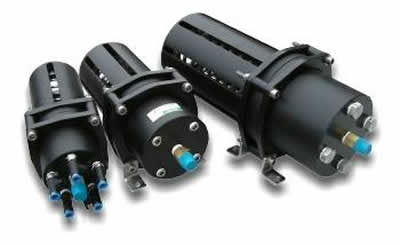
This is a rolling diaphragm, positive pressure compensator (2700cc capacity), manufactured in corrosion resistant plastic suitable for ROV and tooling applications.
These units are particularly suitable for compensating thrusters, compensating oil filled junction boxes, compensating valve packs, and other subsea applications
- Size – 270cc, 2700 cc, 13.5L.
- Delrin Plastic Construction
- Grade 316 Stainless Steel Spring
- Adjustable Pressure Relief Valve
- Mounting Feet
- Low Level Proximity Sensor Option
Motor-pump sets (depth rated to 3000m) for subsea trenching operations.
Silvercrest/SME has recently manufactured and supplied two 265kw motor-pump sets for SMD-Hydrovision (England). The package comprised 265kw subsea motors, 2-pole, 3000v, 3ph, 60hz. Together with Jetting Pumps (wet end only, operating at 2-pole, 60 hertz). The motors were a stainless steel construction, and the pumps Zinc Free Bronze. These motor-pump sets will be installed onto one of the world’s largest subsea trenching vehicles.
In addition, Silvercrest /SME has manufactured and delivered in just eight weeks from order, two water turbine pumps to CTC Marine Projects based in Teeside (England). The pumps will be used by CTC, in conjunction with Silvercrest/SME submersible 260Kw motors, on their subsea plough and trenching vehicles worldwide.
The two Silvercrest SH-M6R submersible pumps with a 231mm OD impeller and a nominal operating speed of 3600rpm will be used as an alternative to the Hayward Tyler model M6-1 stage CI/BR/SS submersible pump.
The Silvercrest pump although matching the performance of the Hayward Tyler unit, is specifically designed for horizontal operation providing a greatly increased reliability for use in horizontal and downward angled operation.
Construction materials:
Pump Castings - AS1830/T260 Grey Cast Iron.
Impeller Casting - PB1 Zinc Free Bronze.
Pump Shaft - SAF2205 Grade Stainless Steel
Shaft Bearings - PB1 zinc free bronze casing. Splined natural rubber.
Upthrust Bearing - PB1 Zinc Free Bronze.
Maximum Pump Thrust - 1470kg at Shut-Off.
Examples of Submersible motors we have manufactured.
SME 10-inch motor, 110kW 2P 400V 50Hz Super Duplex Construction for Service Water Lift Pumps.
SME 6-inch motor, 1.1kW 6P 400V 50Hz Super Duplex Construction for a Hazardous Open Drains Pump.
SME 6-inch motor, 25kW 2P 400V 50Hz Super Duplex for Fire Water Jockey Pumps.
SME 36-inch, 550kW -540HP, 4 Pole, 10000/3/50, Super Duplex Construction Submersible Motor.
SME 36-inch, 1100kW-1475HP, 4 Pole, 10000/3/50, Super Duplex Construction Submersible Motor.
SME 12-inch 150kW 200HP 4 Pole 480/3/60 Super Duplex Construction Submersible Motor c/w 60M of Submersible Cable.
SME 36-inch 2200kW 6-Pole 6600/3/60Hz Super Duplex construction. Submersible Motor.
Submersible motors with 60hz frequency, 1180rpm speed, 6,6KV voltage, and 2000kW power rating. Complete with 50m power cable, and PT100 with 50m instrument cable. To be used as fire water pump drive units.
SME 36-inch, 2200kW, 6 Pole, 6600/3/60Hz, submersible motor. Super Duplex Construction.
SME 36-inch, 2200kW, 6 Pole, 6600/3/60Hz submersible motors.
SME 36-inch, 1800kW, 4 Pole, 6600/3/60Hz Submersible Motor.
SME 36- inch, 1000kW, 8 Pole, 6600/3/60Hz, Submersible Motor
SME ROV24-6, 400kW, 6 Pole, 4100/3/30-64, SS316 Construction Motor, Double Ended to have Water Pump on one end and a Hydraulic Pump at the other end. Max Axial Thrust 100kN, Max Radial Thrust 40kN.
SME SS132-4, 5.5kW, 4 Pole, 400/3/50, SS316 Construction Subsea Motor for Thruster application (reversing Propeller mounted directly on shaft).
SME ROV16-2, 400kW, 2-Pole, 3300/3/60, SS316 Construction Subsea Motor with integral Thrust Bearing nd Interface to suit operation with Water Pump (vertical operation).
SME ROV12-2, 48kW 65HP, 2-pole 3000/3/50, Aluminium Construction ROV Motor fitted with Rexroth A10VO28DFR1/31R-PSC62N00 Hydraulic Pump. Motor to have Burton Connector for Power Leads. Fitted with Temperature Sensing and Water Detectors terminated on Subconn or similar connector. Power Conductor and Sensor Connector Blocks to be in the same position on the motor at opposite ends (or as requested). Epoxy coated for protection.
4kw submersible motor, to be connected to a worm drive and gearbox. Supply voltage 440V, three phase. SME ROV10-4, 4kw, 4 Pole, 440V 50/60Hz, SS316 Construction Subsea Motor
SME ROV14-4 75Kw/100HP, 4-pole, 3000/3/60, anodised aluminium subsea motor. Double-ended motor with Interface to suit Sauer and awasaki Hydraulic Pumps.
300 kW electric motor, 1800 rpm, 4160V 60Hz, electric supply, with adaptation flange to fit with Sauer Danfoss hydraulic pump 90 R 250 type, standard splined shaft.
Electric motors, 1800 rpm, 4160V 60Hz electric supply, each with adaptation flange to fit with Sauer Danfoss hydraulic pump 90R130 type, standard splined shaft. These motors are used on a undersea trenching machine.
SME ROV14-4, 66kW/88HP, 4-pole, 3000/3/60, Anodised Aluminium Subsea Motor, with Interface to suit Hydraulic Pump.
SME ROV10-2, 75HP, 2 – Pole, 3000/3/60, SS316 construction. Subsea Motor fitted with SMP 9WH-4 Stage NAB Construction Pump to provide 4000L/M at 5Bar or 1060GPM at 170ft Head. Motor is oil filled and externally compensated. Tube connection for Power and Subconn or equivalent connector for Water Detector and Temperature Monitoring.
SME ROV22-14, 120HP, 14-Pole, 3000/3/60, SS316 construction. Subsea Motor fitted with Jetech 15055-UW-H Subsea Quintuplex High Pressure Pump to provide 50L/M at 850Bar. Motor is oil filled and externally compensated. Tube connection for Power and Subconn or equivalent connector for Water Detector and Temperature Monitoring.
SME ROV22-12, 120HP, 12-Pole, 3000/3/60, SS316 construction. Subsea Motor fitted with Jetech 100J3-UW-H Subsea Triplex High Pressure Pump to provide 46L/M at 850Bar. Motor is oil filled and externally compensated. Tube connection for Power and Subconn or equivalent connector for Water Detector and Temperature Monitoring.
SME ROV14-100HP 4 pole 3000/3/60 Anodized Aluminium Construction Motor fitted with Rexroth A10VO85DFR1/53R-PUC62N00 Hydraulic pump giving 145l/m at 207 Bar.
Rewind and full service of 150kw Curvetech Motor.
Full Factory Rewind and service of 150/200hp, 1750rpm, 3000/3/60, Curvetech motor at our factory in Perth Australia.
Our standard refurbishment programme includes the following:
- Strip down and through inspection of the complete motor.
- Cleaning and anti-corrosion treatment as required.
- Shaft seal replacement (as may be required)
- Drive end-bearing replacement if required.
- Motor Insulation and Dynomometer testing.
- Motor rewind.
- Rebuild of the complete motor, test and despatch by sea or airfreight.
Any further work deemed necessary as a result of the factory inspection will be quoted separately, and a decision given by the customer as to the course of action required on an item-to-item basis
Submersible motor for operations at 6000m.
We can offer our SME ROV22-12, 150kW, 12-Pole, 500rpm, 3300/3/50, SS316 Construction Subsea Motor. This motor will be manufactured to your exact requirements, and to interface with your submersible pump.
SME ROV14-2, 186kW 250HP, 2-Pole, 3300/3/50, SS316 Construction Subsea Motor, with Flange and shaft to interface with Water Pump.
Submersible Motor. Power 15 kW, Speed 2910 1/min, voltage 3.3kV, working depth 300m. SME ROV10-2, 15kW 20HP, 2-Pole, 3300/3/50, SS316 Construction Subsea Motor, with Flange and shaft to interface with Water Pump.
SME 400kw 4-Pole 1500rpm 3300/3/50 Submersible Motor.
SME 400kw 4 Pole 1500rpm 6600/3/50 Submersible Motor.
SME 145kw 8 Pole 1500rpm 3300/3/50 Submersible Motor.
SME 145kw 8 Pole 1500rpm 6600/3/50 Submersible Motor.
SME ROV18-4, 300kW, 4 Pole, 1800rpm, 3000/3/60, SS316 Construction Subsea Motor to drive Hydraulic Pump.
SME ROV10-4, 40kW, 4 Pole, 1800rpm, 3000/3/60, SS316 Construction Subsea Motor to drive Hydraulic Pump.
SME 10-inch, 37kW 50HP, 2 Pole, 380/3/50, Ni Al Br Construction Submersible Motor, with Modified Shaft and Flange to replace a Hayward Tyler MS 201-50 Motor and pump.
SME 10-inch, 37kW 50HP, 2 Pole, 380/3/50, Super Duplex Construction Submersible Motor with Modified Shaft and Flange to replace a Hayward Tyler MS 201-50 Motor and pump.
SME ROV14, 250kW, 4 Pole, 3000/3/50, SS316 Construction Subsea Motor fitted with A4VG250EP4D1/32R-NSD10F001DP Hydraulic Pump.
SME ROV14, 250kW, 2 Pole, 3000/3/50, SS316 Construction Subsea Motor to Drive Water Pump.
SME ROV14-4, 60kW, 4 Pole, 3000/3/50, SS316 Construction Subsea Motor fitted with A4VG40EP4D1/32R-NSC02F013DP and A10VO28DFR/31R-PSC62K01 Hydraulic Pumps at either end.
SME ROV14-4, 150kW 200HP, 690/3/60, Anodised Aluminium Construction Subsea Electric Motor. Fitted with a Rexroth A11VLO260LRDS/11R-NTD12N00 (CW ROTATION) PUMP-PISTON-VARIABLE at one end, and a Rexroth AZPW-2x-019-022LRRXXMB-SO593P (CCW ROTATION) PUMP-SINGLE-GEAR-SAE`A` 19cc, at the other end. Motor will have Oily tube for Power, and Subsea Connector for Temperature and Water Ingress Sensors. Motor available in SS316 stainless steel if preferred.
Motor Rewinds and Refurbishment.
Our standard motor refurbishment and rewind programme includes the following:
- Strip down and through inspection of the complete motor.
- Cleaning and anti-corrosion treatment as required.
- Shaft seal replacement (as may be required)
- Drive end-bearing replacement if required.
- Motor Insulation and Dynomometer testing.
- Motor rewind.
- Rebuild of the complete motor, test and despatch by sea or airfreight.
6.6Kv Motors Available.
We have manufactured many 6.6kV motors, mainly Submersible Pump Motors for various Mining, and Offshore applications. Usually we supply to Pump Manufacturers who fit these motors to their pumps. We can offer the following motors, subject to agreed technical drawings:
SME ROV22-4 300kW 4 Pole SS316 Construction 6600/3/60 Subsea Motor to drive Hydraulic Pump.
SME ROV18-4 300kW 4 Pole SS316 Construction 4100V Subsea Motor to drive Hydraulic Pump.
SME ROV22-4 300kW 4 Pole SS316 Construction 4500/3/60 Subsea Motor to drive Hydraulic Pump.
The method of construction changes at 4100V from Random Wound to Formed Coils so there is a jump from 4100V to the 4500V motor. The 4500V motor is constructed very similarly to the 6600V Motor.
Silvercrest will bespoke manufacture virtually any shape and size of submersible motor and submersible pump required for subsea operations. We can offer a wide range of HPU and motor-pump sets complete, subject to any modifications, and changes you may require. For example:
SME ROV12-2 48kW 65HP 2-pole 3000/3/50 Aluminium Construction ROV Motor fitted with Rexroth A10VO28DFR1/31R-PSC62N00 Hydraulic Pump. Motor to have Oily Tube connection for Power Leads. Fitted with Temperature Sensing and Water Detectors terminated on Subconn or similar connector. Epoxy coated for protection.
SME ROV14, 200kW, 268HP, 4 Pole, 3000/3/50, 1490rpm Stainless Steel Construction Subsea Motor designed to close couple to Rexroth A11VLO190DRS-11-LN-12N00 Hydraulic Pump.
SME ROV10-4, 50HP, 4-Pole, 1000-3000/3/50 Anodised Aluminium Construction Subsea Motor. Fitted with Rexroth A10VO45DFR1/3xR-PSC62N00 Hydraulic Pump to provide 66L/m at 200 Bar. Motor fitted with Oily Tube connection for Power and Earth. Temperature and Water Detectors terminated in Subconn Connector. Hydraulic pump close coupled to Motor.
SME ROV14-2 motor, 265kw 2-pole 3000/3/60 with Stainless Steel Construction. Fitted with a PTS Sterling 350D-1 ZFB Pump (wet end only). Operating at 2- pole, 60 hertz. Thrust developed at duty: 1820kg. Thrust at Shut-off: 3016kg. Approx. length of pump: 750mm. Bowl diameter: 340mm.
SME ROV14-2 300kw 2 pole 3000/3/60 Oil filled Stainless Steel Motor with In built Circulation System and Heat Exchanger coupled to a Sterling 300M-3 Zinc Free Bronze Pump with a duty of 828cu.m/hr at 9 Bar.
ROV20-4 type motors, 4 pole/6600vac/3 phase/60hz, with stainless steel construction. Double Ended for fitment with Sauer hydraulic pumps Series-90, with Subsea Connectors for Power and Sensors. We can offer the ROV20 motor with shafts at both ends, to mate with the Sauer Series 90 pumps .
SME ROV24-6, 400kW, 6-Pole, 4100/3/30-64, SS316 Construction Motor. Double Ended to have Water Pump at one end, and the Hydraulic Pump at the other end.
SME ROV228, 325kW, 8-pole, 3300/3/60, SS316 construction, Subsea Motor to drive Water Pump.
SME 36-inch 2200kW 6-Pole 6600/3/60Hz Super Duplex construction. Submersible Motor manufactured for a shaft down application. Motor fitted with 4 x PT100 (3 internally in the windings, 1 on the thrust bearing ). Suitable for connection to CD pump.
SME 36-inch, 550kW -540HP, 4 Pole, 10000/3/50, Submersible Motor, Super Duplex Construction.
SME 36-inch, 1100kW-1475HP, 4 Pole, 10000/3/50, Submersible MotorSuper Duplex Construction.
SPECIFICATIONS FOR SME SUBSEA ELECTRIC MOTORS.
SME can design and build SUBSEA motors to suit any requirement due our totally flexible design
capabilities:
 Flexible External Dimensions to suit all applications. Flexible External Dimensions to suit all applications.
 Dimensions to allow drop in replacement for existing units. Dimensions to allow drop in replacement for existing units.
 Anodised aluminium, or, 316 stainless steel. Anodised aluminium, or, 316 stainless steel.
 Power drive to load using an output shaft with a standard coupling, or, close coupled, etc. Power drive to load using an output shaft with a standard coupling, or, close coupled, etc.
 Single drive shaft, or, a drive shaft at both ends, (double shaft extension). Single drive shaft, or, a drive shaft at both ends, (double shaft extension).
SME can design and build a motor with a completely new lamination to meet special design requirements, if necessary.
SME design their motors so they do not run hot. Typical motors can run on deck for at least 10 minutes on full load, with no cooling, without overheating. The motors are designed to be compact in size and suitable for heavy duty applications, like trenching.
If weight is important SME can design the motor for minimum weight by utilising an aluminium construction and a hollow motor shaft, etc., while still ensuring the motor is generously rated for full load operation. If the motor is going to drive a hydraulic pump we recommend a close coupled arrangement to save the weight of the coupling and the coupling housing.
SME can design and build motors for all voltages from 24 Volts to 6600 Volts with 50Hz or 60Hz frequencies, or for VVVF requirements. High Voltage motors can have random stator windings, or formed coils, depending on space and weight constraints. The winding wire for the High Voltage motors is double insulated and passes a twisted wire test at 16,000 volts and is rated up to 155 Deg.C.
All windings are designed to keep 'turn to turn' voltage to a minimum. All winding materials and cables, etc. are specially selected to be suitable for use in hydraulic oil.
In general the SME SUBSEA motors have low loss lamination steel (3 Watts/kg), which allows for higher flux densities, and less heat, with less material and weight.
All motors are oil filled and we recommend hydraulic oils for good lubrication characteristics in preference to electrical oil which has better di-electric capabilities, but worse lubrication capabilities.
If motors are going to drive a water pump SME can design the motor to take the thrust load from the pump, and keep the sea water out of the motor with a single or double mechanical seal arrangement.
Thruster motors can be designed and built for voltage/speed control, which is a relatively simple speed control system, and they can also be built with a thrust bearing incorporated to take the thrust load from the impeller.
To ensure the integrity of the motor housing SME does not use castings. All components are machined from solid or from extrusions. The external aluminium components are typically 6061 T6 marine grade aluminium and hard anodised to a military specification.
All ball bearings are from well known brands such as SKF, FAG, or NSK. Oil seals are high temperature and typically made from Viton. Mechanical seals are typically Burgmann.
All hardware used on SME SUBSEA motors is 316SS.
All fixing holes are blind except the "oil in" and "oil out" fittings and the stator pack fixing bolt, if applicable.
The preferred power cable entry system for SME motors is to use an "oily tube" connected to an adaptor that is part of an oil tight rubber gland, which is fixed to the stator frame. SME do not recommend bringing the power cables through the end shields of the motor because this creates additional complications when the motors are stripped down during service, because the end shields cannot be readily removed from the stator. Subsea connectors can be offered as an alternative to the Oily Tube if requested.
SME strongly recommend that the motors are supplied with PT100s fitted in the windings and also in the bearings and that the internal motor temperatures are monitored and set up to alarm if the temperatures rise above the "norm". SME can also offer additional protection with a water detector, etc. The auxiliary connections for PT100s, etc. can be made through standard high pressure, water- tight, plug and sockets as supplied by "Subconn", "Impulse", and "Burton". These are also fitted to a connection block on the stator, not on the end shield.
All finished motors are pressure tested to ensure they are "oil tight" and suitable for compensated operation down to 4000 metres.
All motors are rated for continuous operation and all prototype motors are full load performance tested rated voltage and rated frequency to confirm their performance characteristics. All motors can be issued with a "Type Test Certificate" or even full load tested at additional cost, if required.
SME can also offer to arrange for hydraulic pumps to be set up and tested on the motors at rated voltage and frequency.
SME can offer to supply Hydraulic Power Units complete with the addition of a customer specified Hydraulic Pump.
SME is a fully quality assured company to ISO 9001.2000 for "Design, development, manufacture, and testing of submersible electric motors and electric motors for remotely operated vehicles".
SME Subsea motors can be designed and built for all subsea applications, such as ROVs, Trenchers, Ploughs, Submarines, Dredges.
All makes of subsea motor can be serviced, repaired and tested by SME. In some cases the original motors can be significantly upgraded. If you are having problems with your existing subsea motors please contact SME - we are keen to help and we are very price competitive.
At SME we are continually working on improving the performance of our products and for this reason we reserve the right to make changes without notice to any of the data in this brochure.
SME design, manufacture, and supply, submersible electric motors for bore-holes. SUBSEA and ROV electric motors for SUBSEA equipment. Submersible electric motors for sump pumps, and any special purpose submersible electric motor requirements. SME also offer SUBSEA electric generators for Tidal Power Generation.
 Repair and rewind of large high voltage (500kW, 6600V) submersible electric motors. Repair and rewind of large high voltage (500kW, 6600V) submersible electric motors.

 SME High Temperature Submersibles in 6 inch to 20 inch frames suitable for operation in ambients of 75 Deg.C. SME High Temperature Submersibles in 6 inch to 20 inch frames suitable for operation in ambients of 75 Deg.C.

 High Voltage water filled submersible motors (3300V, 4160V and 6600V). High Voltage water filled submersible motors (3300V, 4160V and 6600V).

 Upgraded Temperature Monitoring units available with new improved user friendly parameter setting. Upgraded Temperature Monitoring units available with new improved user friendly parameter setting.

 ROV motors suitable for depths of 4000M. ROV motors suitable for depths of 4000M.

 WD Series sump pump motors. WD Series sump pump motors.

 Subsea Electric Generators for Tidal Generation. Induction Generators or slow speed Permanent Magnet Synchronous Generators up to 500kW. Subsea Electric Generators for Tidal Generation. Induction Generators or slow speed Permanent Magnet Synchronous Generators up to 500kW.
SUBMERSIBLE MOTORS.
SME has many years of experience with the design and manufacture of submersible motors, used in the offshore and dredging industries. This experience has resulted in SME being the company of choice as a manufacturer and supplier for many of the major offshore subsea companies
SME submersible motors are specially designed to suit customer requirements. With special attention being paid to the motor design. Resulting in SME manufacturing rugged motors with low maintenance requirements, a very high reliability, and a long service lifetime. Low speed designs are available up to 1.0 MW leaving out the need for a gearbox.
SME submersible motors have a generous overload margin with solid lamination, windings and rotor design. The SME submersible motor can be oil filled. Hence no re-greasing of the bearings is required. The oil filling also prevents condensation of water inside the motor. Cooling of the motor can be either by natural cooling or forced cooling by the surrounding seawater.
The following instrumentation is available:
Stator temperature measurement, Bearing temperature measurement
Oil temperature measurement
Pressure difference transmitter Seawater / Oil
Water leakage detection in auxiliary connection boxes
Factory load test
Horizontal or vertical mounting of the motor.
SME offer a Repair and Re-conditioning service for your used submersible electric motors. In addition to the manufacture of new submersible motors, we also carry out maintenance, repair and re-conditioning of submersible motors of our own design and third party motors. After Sales Support . Maintenance, repair and overhaul of large electrical motors of any make and type.
Winding and Electrical Test Procedures for Submersible Motor Engineering.
Minimum Test Requirements for New or Rewound Stators prior to Assembly are as follows:
1000 Volts to 3300 Volts - Wet Wound Motors.
Whole stator is submerged in water and pressurized to 30 psi for 30 minutes and then Hi Pot tested at Rated Voltage x 2 + 1600 Volts for 1 minute.
380 Volts to 1000 Volts.
Whole stator is submerged in water and pressurized to 30 psi for 30 minutes and then Hi Pot tested at Rated Voltage x 2 + 1600 Volts for 1 minute.
Minimum Test Requirements for Stators during Assembly are as follows:
1000 Volts to 3300 Volts.
1. Insulation Resistance Test - Megger Test - 5000 Volts DC for 1 minute.
2. Dielectric Absorption Test - Megger Test - 1000 Volts DC for 10 minutes.
3. Hi Pot Test - Rated Voltage x 2 + 1600 Volts for 1 minute for new or rewound stators. Rated voltage x 2 for 1 minute for reconditioned stators.
4. Surge Test at 2000 Volts DC.
380 Volts to 1000 Volts.
1. Insulation Resistance Test - Megger Test - 1000 Volts DC for 1 minute.
2. Dielectric Absorption Test - Megger Test - 1000 Volts DC for 10 minutes.
3. Hi Pot Test - Rated Voltage x 2 + 1600 Volts for 1 minute for new or rewound stators. Rated voltage x 2 for 1 minute for reconditioned stators.
4. Surge Test at 500 Volts DC.
Tests are to be performed in the sequence specified.
The Engineering Department is to be consulted immediately if any Stators fail a test.
If the polarization Index is less than 2, consult the Engineering Department.
Pass/Fail criteria are based on IEC standards, IEEE Standards, and the Baker Surge Test Manual.
Test motor with a full set of BJM tests and record the results.
No Load Running.
Run Motor on No Load - preferably in the Vertical position.
Adjust voltage and frequency to match Nameplate voltage and frequency.
Record: Voltage on all 3 phases, amps on all 3 phases, RPM, Vibration Levels at DE and NDE in both planes, time motor takes to stop after power off.
Compare results with standard figures and other similar motors. Advise Engineering Department immediately if there is a discrepancy.
 Effect and Results of Water in Leads. Effect and Results of Water in Leads.
|
|
|
|
|
Water in Leads |
Fault in 1 lead |
Fault in 2 leads |
Fault in 3 leads |
Winding Currents (Most motors are internally connected in Delta). |
Unbalanced currents. High Insulation Resistance to Earth 1 to 2 x FLC, Light Load on motor 2 to 3 x FLC, stalled motor 4 to 6 x FLC. |
Unbalanced currents. High Insulation Resistance to Earth 1 to 2 x FLC, Light Load on motor 2 to 3 x FLC, stalled motor 4 to 6 x FLC. |
Unbalanced currents. High Insulation Resistance to Earth 1 to 2 x FLC, Light Load on motor 2 to 3 x FLC, stalled motor - probably no current in motor winding. |
Current in Dry leads |
1 to 6 x FLC |
1 to 6 x FLC |
N/A |
Current in Wet leads |
Current flow to Earth = 20 x FLC |
Current flow to Earth = 20 x FLC |
Current flow to Earth = 20 x FLC |
Failure |
Burnt out Winding. Overheated Motor lead. |
Burnt out Winding.Overheated Motor lead. |
Burnt out Winding.Overheated Motor lead. |
Recommended Protection |
Fast Acting Earth Leakage Relay.Fast Acting Overload Relay or Circuit Breaker. |
Fast Acting Earth Leakage Relay.Fast Acting Overload Relay or Circuit Breaker. |
Fast Acting Earth Leakage Relay.
Fast Acting Overload Relay or Circuit Breaker. |
|
|
|
|
On a correct installation the motor frame is earthed. Water is a good conductor of electricity. As soon as a circuit is established between the water in the bore and the power supply cables, current will flow through this fault causing unbalanced currents in excess of normal Full Load Current (FLC). If the motor is not disconnected from the supply immediately catastrophic damage will be caused to the windings due to overheating because of high currents.
The magnitude of the current flows will depend on the level of insulation to earth. Sometimes these faults are not solid connections to the water or to earth, i.e. there is still a high insulation level to earth, which restricts the current flow to earth. In this case the Earth leakage and/or overload protection may not trip immediately and the motor windings still overheat due to the unbalanced currents.
|
 Evidence of Water in the leads. Evidence of Water in the leads.
|
|
When the motor leads or drop cables are cut, water drains out when the leads are held up in the air and the recently cut end is left hanging down.
Stator winding are overheated usually causing multiple earth faults in the windings.
|
Submersible Motor Engineering motors have been extensively tested and used with modern GTO and IGBT VVVF Drives, however, care must be taken to ensure reliable and satisfactory operation. Please pay attention to the following guidelines.

|
Accurate and Calibrated Quick Trip overloads must be installed and set to trip if the current in any phase exceeds the full load current.
|

|
The motor should not be operated continuously at less than 70% of Synchronous Speed - 3000 x .7 = 2100 RPM for a 50 Hz 2 pole motor, or 1500 x .7 = 1050 RPM for a 50Hz 4 pole motor.
|

|
Maximum Speed is the nameplate synchronous speed ¨C 3000 RPM for a 50 Hz 2 Pole motor and 1500 RPM for 50 Hz 4 Pole Motor.
|

|
Maximum Run Up time must not exceed 4 seconds.
|

|
Maximum Run Down time to Power Off shall not exceed 4 seconds.
|

|
Cooling water flow past the motor must exceed 15 cm/sec or 0.5 feet/sec at all times and under all operating condition except during Start Up, however, water flow should not exceed 300 cm/sec or 10 feet/sec as this can also create an overheating condition.
|

|
The VVVF Drive must be set up to supply a constant linear Volts to Hertz ratio, i.e. at 25 Hz the Voltage should be 207 Volts for a 415 V 50 Hz motor.
|

|
The output of the VVVF Drive should be filtered to reduce harmonics. The output power should be balanced, free of High Voltage Transients, and harmonics, and within the rated voltage and frequency of the motor. |
Operation at reduced speed can cause overheating. Operation with a long Run Up time can cause problems in the Down Thrust bearing, due to insufficient lubrication between the Pivot Shoes and the Carbon Thrust Bearing Disc. Other operating requirements still apply as specified in Submersible Motor Engineering Installation and Maintenance Procedures.
Overheating in Submersible Motors
The most common cause of failure in a Submersible Electric Motor is Overheating, as this causes the insulation materials in the motor to deteriorate until failure occurs. Sometimes the overheating can introduce other problems in the motor, before it fails, which accelerates the process.
The most common causes of overheating are as follows:
Overloading.
High ambient water temperature.
Low flow rate of external cooling water.
Very high flow rate of external cooling water.
Low Supply Voltage.
High Supply Voltage.
Incorrect Installation Procedures.
Voltage and Current Unbalance.
Voltage surges and Spikes.
Single Phasing.
Phases Reversed.
Build up of organic or mineral material on the outside of the motor.
Rapid cycling - switching the motor on and off frequently and quickly.
Incorrect Ramp Up time when using a Soft Starter ¨C Maximum 4 seconds is allowed. DU has a separate bulletin covering the use of submersible motors with VVVF Drives and Soft Starters.
The Effects of Overheating on different parts of the motor are as follows:
Internal Cooling Fluid. The fluid will boil which will create steam inside the motor at high pressure. The steam will force it's way out of the motor, past the lip seals on the DE, or the Mechanical seal on the DE, or it can rupture the rubber bellows on the NDE. Steam will not transfer the heat from the internal components such as the stator windings or the rotor.
Stator Windings. Without efficient heat transfer in the cooling fluid the insulation will breakdown and short circuits and or earth faults will occur. If the fault is violent other parts of the motor can be damaged such as the lamination stack.
Bearings. The carbon sleeve bearings and thrust bearing will fail very rapidly without efficient fluid lubrication. Usually this occurs first in the upper sleeve bearing and leads to binding, rapid wear, and misalignment for the pump and the rotor.
Rotor. If the sleeve bearings wear sufficiently this can allow the rotor to rub against the stator, which is called ¡°poling¡±. This will cause localized high temperatures, and mechanical problems, that will quickly lead to catastrophic failure of the motor. It is quite common for some of the stator teeth to be dragged into the stator slot and cut through the wires in the stator winding, creating an earth fault.
Bellows or seals may deteriorate and rupture allowing the external fluids and foreign matter to enter the motor. The foreign matter can be abrasive, which will encourage wear if the motor continues to run.
Casings and Housings. In extreme situations it may be possible for the casing of the motor or the end brackets to warp and cause misalignment.
If the motor is subject to electrolysis, or bacteria build up, this can accelerate due to higher temperatures, which in turn will cause even higher temperatures.
Possible Reasons for Overheating
Overloading is usually caused by:
Excessive hydraulic load.
An oversized, or wrongly sized, pump fitted to the motor.
Misalignment.
Binding.
Failure of a component in the motor or the pump,
Foreign bodies, or solids, in the water being pumped.
Over frequency. Motors must be correctly selected to match the pump and the duty required.
If a motor is powered from a Generator Set, rather than the mains of a power utility it is possible that the supply frequency is higher than motor/pump design frequency. The characteristics of normal pumps are very sensitive to speed. Increased speed due to increased frequency will almost certainly raise the duty point of the pump and this can cause the motor to be overloaded.
Overloading of a motor will almost certainly cause overheating, however, overheating will not necessarily cause overloading.
High Ambient Water Temperature
Submersible Motor Engineering specify the maximum ambient water temperature, the minimum cooling water flow in m/sec, and the maximum full load output power for the motor. All of these conditions can vary in practice and this will affect the ability of the motor to dissipate the internal heat that is generated by the motor in operation. If the motor overheats because the maximum ambient cooling water temperature is exceeded the life of the motor will be reduced.
Low/High External Cooling Water Flow
The motor relies on the efficient transfer of heat from the external surface of the motor to the water flowing past the motor. If the flow is too slow the external water will heat up and create a similar condition to having a high ambient water temperature. Low flows are usually caused by:
Low Pump flow rate.
Incorrect application or design.
Plugged or blocked suction inlet.
Loss of suction.
Closed or blocked discharge.
Low pump speed.
Loose impeller or impellers.
Water flow into the pump from above the motor.
Motor installed below the well screen.
Pump suction inlet set at the same level as the well screen.
Large gap between the motor and the well liner.
Obstruction around the motor.
Motor buried in sand or silt.
Motor/Pump installed without a shroud in a tank or pit.
Motor/Pump installed in water with a very high concentration of Oxygen. If the external cooling water is flowing too fast it may form a recirculating or turbulent layer along the surface of the motor. This layer may prevent the external surface of the motor from being able to dissipate the heat fast enough to cool the motor. High velocity flow conditions also cause a decrease in pressure which may cause dissolved minerals to precipitate out of the water forming a mineral plating on the surface of the motor which will also act as a form of thermal insulation and reduce the cooling capacity even further.
In some wells bacteria will grow on the external surface of the motor ¨C in extreme cases this can be a much as 10mm in 3 months. This bacteria growth also acts as thermal insulation and as it grows out towards the well liner it will force the external water flow rates to increase as the gap between the well liner and the bacteria surface on the motor reduces eventually causing excessive flow rates.
Low/High Voltages
Low voltages will lead to increased currents, as voltage and current are generally proportional if saturation effects are neglected. Increased currents will lead to increased heating in the stator winding. Low voltages will also lead to lower full load speed and increased slip. The pump will have a reduced performance leading to reduced water flow past the motor and possibly reduced cooling capacity.
High voltages will lead to a reduced stator current, until the voltage is sufficiently high that the lamination iron starts to saturate, at which point the current will start in increase leading to increased temperature rise. High voltages will also cause the motor to have increased starting torque and increased starting current, which will probably lead to higher temperatures during starting.
Incorrect Installation Procedures
The pump and motor must be assembled correctly. Any Misalignment or Binding can cause overloading of the motor.
Misalignment occurs when components are not machined correctly or not assembled correctly. All the components in the motor and the pump must be concentric within the tolerances specified by the manufacturer. Special attention must be paid to component fits, the balance and vibration of rotating components, clean assembly conditions with no foreign objects or matter in the assembly,
Binding is usually caused because there is insufficient room for axial or radial movement in the pump or because the shaft coupling is not fitted correctly. The coupling should not be pinned or fixed with a grub screw to the motor shaft ¨C it should be free to slide on the shaft to allow for thermal expansion of the motor shaft.
All water filled motors must be correctly filled prior to installation as the motor relies on this water to remove the heat generated in the water. If a motor is not properly filled there is a strong possibility the motor will overheat.
Great care must be taken during installation to ensure that whole motor/pump assembly is not damaged. Special care must be taken when lifting the motor/pump to the vertical position prior to lowering down the hole. Make sure the shaft is not subjected to excessive bending forces, which can bend the shaft.
Voltage and Current Unbalance
This is probably the single most common cause of motor failure. Generally this is caused by voltage imbalance, leading to current unbalance. Unbalanced currents will definitely lead to increased temperature rise in the stator winding. If the motor is fully loaded ¨C not de-rated ¨C it will almost certainly lead to stator windings exceeding safe temperature limits.
DU motors require that the Voltage balance must be within 3%.
Voltage Unbalance can be calculated using the following formula:
Voltage Unbalance % = 100 x Max. Voltage variation from Average / Average voltage.
DU has a separate bulletin especially covering Voltage and Current Unbalance.
Voltage Surges and Spikes
A High Voltage Surge is when the supply voltage increases substantially for a period of milliseconds or seconds. A spike occurs when there is a very high voltage transient for nanoseconds or milliseconds.
A surge is quite likely to occur when a generator supplying a motor runs out of fuel. When the fuel mix becomes very lean the engine speeds up and the output voltage from the generator increases. Spikes are usually caused by the switching of electrical equipment on the supply system ¨C not necessarily the actual contactors or circuit breakers operating the motor. Very large surges or spikes can be caused by indirect lightning strikes on the supply system.
This is a complex subject, however, in general, small voltage increase/short duration surges will tend to stress the windings causing gradual deterioration over a period of time, and eventually catastrophic failure of the windings.
Large voltage increase/long duration surges will severely stress the winding and connection points ¨C the weakest point in the winding or connections will fail usually causing a short circuit which can have enough energy to blow a hole in the lamination pack or even through the stator casing.
Small spikes will stress and degrade the windings and connection, while a large spike will almost certainly lead to immediate catastrophic failure.
Single Phasing
Single phasing occurs when 1 phase of a 3-phase supply is lost, i.e. there is no voltage on one phase.
In a Delta connected motor current will continue to flow in all 3 phases of the winding, but extremely high currents will flow in the phase connected directly between the 2 remaining voltage connections ¨C this phase will overheat and fail very quickly if the motor is not shut down very quickly.
In a Star connected motor current will continue to flow in the 2 phases connected between the 2 remaining voltage connections ¨C these 2 phases will overheat and fail is this condition is not detected very quickly and the motor disconnected from the supply.
If the motor is not operating and is switched on to a Single Phasing supply it will almost certainly not start and will draw high starting current as described about until it is disconnected. If the motor is already running and 1 phase drops out for whatever reason the motor will probably continue to run at reduced speed while drawing heavy current.
Phase Reversal
Phase reversal will result in the motor running in the wrong direction and in general the pump will operate very inefficiently, probably not drawing enough water past the motor to cool it properly.
Build up or organic or mineral material on the outside of the motor
Organic deposits are usually caused by iron bacteria. These bacteria produce a layer, or crust, of iron and/or magnesium compounds on the outside of the motor. These encrustations act as a thermal barrier and contain the heat within the motor. The presence of iron bacteria is usually a pre-existing condition.
Mineral deposits will cause the same type of thermal barrier as organic deposits. Chemical reactions precipitate the minerals present in the water and deposit them on the external surface of the motor. The most common mineral deposits are carbonates, iron, manganese, and silicates.
Rapid Cycling
Rapid cycling causes the motor to overheat, as it does not get sufficient time to cool down from the previous start/run. When a motor is started it draws 4 to 6 times the normal full load current. This increased current creates high temperatures in the stator and rotor windings. This is especially a problem if the motor is already hot because it has been operating at its nominal full load temperature. Several starts in quick succession will almost certainly cause the motor to overheat which will cause a degradation of the stator winding insulation and other internal components. Eventually the deteriorated conditions inside the motor will cause it to fail.
DU recommends that motors be allowed to cool for 15 minutes before being restarted. In some circumstances motors may require even longer to cool down, especially if the ambient water temperature is high.
DU also recommend that a motor is allowed to run for about 1 minute after start up to allow the heat generated during the starting cycle to partially dissipate.
The whole installation should be designed to keep the number of starts required by the motor to a minimum, which will increase the life of the motor.
Summary
Motor overheating is usually a symptom of other problems. Failure to investigate and determine the true reason for the overheating will lead to motor failures, extended down times, repeated repairs, and higher maintenance costs.
Unbalanced Currents and Submersible Motors
One of the most common causes of failure in Submersible Electric Motors is because of overheating due to unbalanced currents, usually caused by unbalanced voltages. IEC Report 892:1987 (AS1359.31 1997) states: "The application of unbalanced voltages to a three phase induction motor introduces a "negative sequence voltage", and this produces in the air gap a flux rotating against the rotation of the rotor, thus tending to produce high currents. A small negative sequence voltage may produce currents in the windings that are considerably in excess of those present under balanced voltage conditions. Consequently the temperature rise of the motor operating on a particular load and percentage voltage imbalance will be greater than for the motor operating under the same conditions with balanced voltages." This applies for all induction motors, but is especially critical for submersible motors because they operate at much higher current densities than standard air cooled motors and have a much lower tolerance to increased temperatures. If voltages are unbalanced then currents will almost certainly be unbalanced. Even if the voltages are balanced it is possible to have large current unbalance - if this is the case it is usually caused by the way the drop cables are arranged in the well. For example, we recently helped a customer experiencing 20 amps current unbalance with a 150Hp 8 Inch motor on full load, when the voltages were balanced within 1 volt at the surface. The drop cables had been tied to the flexible column with 2 phases on one side and 1 phase and the earth cable on the other to give a better mechanical balance. When the cables were rearranged with the 3 phases tied together on one side and the earth on the other side the currents were balanced within 2 amps. This large variation in current was caused by magnetic field linkage and interaction between the 3 phases, which was amplified over 250 metres of cable down the hole. We can expect increased, uneven, and localised heating in a motor because of unbalanced currents, so it is essential to ensure that the voltages and currents are balanced when motors are commissioned. If the voltage supply to the motor is solid and stable the currents will probably remain reasonably balanced, however, on some sites, such as mine sites, large variations can occur during the day as different parts of the plant are operated and alter the supply conditions. In this type of supply environment SME strongly recommend that voltage and current unbalance protection is included in the motor protection system. Voltage unbalance is more common in rural areas where there can be large single-phase loads, which unbalance the supply. To get an idea of the effect of voltage and current unbalance; for 1% voltage unbalance we can expect about 8% current unbalance and 10% increase in temperature rise. The correct way to calculate the percentage Current unbalance is to use the formula below:
Percentage Current Unbalance = (Maximum current difference from average current / average current) x 100
Procedure.
Measure the currents in all 3 phases.
Add the 3 measured currents and divide the total be 3, which gives the average current.
Calculate the amps unbalance for the worst phase by subtracting it from the average.
Divide the worst-case unbalance amps by the average and show as a percentage. This figure is know as the Percentage Current Unbalance and it should not be more that 5% for SME motors. (Most manufacturers do not allow more that 5% current unbalance).
Example:
Currents measured are 34, 36, and 40 amps.
The total of the 3 currents is 110, and the average is 36.67 amps.
Worst Case unbalance is 40 - 36.67 = 3.33.
Current Unbalance is 3.33 / 36.67 = 9%
A motor seldom has completely balanced currents even if the voltage supply is balanced so in some cases it is possible to balance the currents by rotating the motor connections. This should be done by moving all 3 connections in the same direction each time so that the direction of rotation of the motor is not changed. The currents should be recorded for each phase with reference to the supply and motor terminals. All 3 connection options should be tried and then the connection that gives the best result should be used.
If there is still significant current unbalance after the current unbalance has been reduced to a minimum by rotating the phases then it may mean considering de-rating the motor. This either means reducing the pump output by fitting a smaller pump or maybe by removing an impeller, or installing a larger motor. 5% current unbalance probably means that there is about 0.8% voltage unbalance.
As an alternative to derating it is possible to measure and monitor the actual temperatures in the motor using PT100s. SME fit 3 PT100s in the windings and in the slot as standard for all motors 8 Inch and above. In general SME will know where the winding hot spot is for different motors and they can then advise if it is safe to operate the motor when the actual temperatures are known, even if there is high current unbalance. In some cases the ambient water temperature may be low, or, the motor is not fully loaded by the pump, so the actual winding operating temperature will still be well within acceptable limits.
Current unbalance in an induction motor has a number of effects, which reduce the performance of the motor, but the most significant for submersible motors is the increase in temperature.
Any installation with more than 5% voltage imbalance is not suitable for use with submersible motors or any type of induction motor. The supply authority needs to fix the problem.
Thrust Bearings
Thrust Bearings in SME Submersible Motors
All SME submersible motors are fitted with Kingsbury type Hydrodynamic Self Adjusting Tilting Shoe Thrust Bearings to take the axial "down thrust" from the pump. These are a complex and clever part of a reliable submersible motor and probably not understood very well.
These thrust bearings will take a surprisingly heavy axial "down thrust" load and provided that they have been installed correctly, rated correctly, and looked after properly, they will provide may years of trouble free operation.
SME motors also have an "up thrust" bearing to take thrusts - usually these occur at start up while the discharge pipe work is filling. The "up thrust" can be significant if pipe work is long between the pump and the surface and the Non Return Valve (NRV) has been drilled to allow the column to drain. While the column is filling there is a large momentum force upwards, and the head, acting down, is low, and the pump is quite likely to be operating beyond its Best Efficiency Point (BEP). The "up thrust" tends to be heavier with closed type impellers. On some pumps the thrust will reverse just after the BEP.
SME recommend that pumps should be operated according to the pump manufacturer's recommendations. Pumps should have a means of accommodating temporary "up thrust" and the splined couplings between the pump and the motor should not be grub screwed.
The "up thrust" bearing in the motor is a fairly simple device, which consists of a resin/cloth fibre ring, which rubs against the underside of the Stainless steel Thrust Bearing Support plate. These bearings are not continuously rated and only take light loads.
Principle: The Hydrodynamic thrust bearing transmits the rotating shaft's axial thrust load to the frame of the motor, which is mechanically supported in the well.
The axial thrust load is transmitted through the bearing on a self-renewing film of lubricant, which is water in most SME motors. The pressure in the fluid film supports the load without the thrust disc or pivot shoes making contact.
Theory: Due to viscosity, fluids tend to stick to surfaces, and in the case of Kingsbury type thrust bearings, they rely on the fluid sticking to the surface of the rotating thrust disc. The fluid is dragged circumferentially as well as being thrown outwards by the rotating disc. At the leading edge of the pivot shoes, a continuous fluid wedge will form. When the right conditions exist the wedge will produce sufficient lift to create a physical separation between the thrust bearing disc and the face of the pivot shoe. At this point a true fluid film (TFF) is said to exist. the fluid sticking to the surface of the rotating thrust disc. The fluid is dragged circumferentially as well as being thrown outwards by the rotating disc. At the leading edge of the pivot shoes, a continuous fluid wedge will form. When the right conditions exist the wedge will produce sufficient lift to create a physical separation between the thrust bearing disc and the face of the pivot shoe. At this point a true fluid film (TFF) is said to exist.
TFF is essential for the successful operation of the thrust bearing. When the bearing is operating correctly there is no contact at all between the disc face and the face of the pivot shoes. The only time there is contact is when the motor is stopping or starting. This brief contact period means there should be only negligible wear between the faces - and no wear while the motor is operating.
The adjacent sketch shows how the pivot shoe tilts over and allows the fluid to be forced between the carbon thrust disc and the face of the pivot shoe by a combination of rotational drag and centrifugal force. The pivot point should be spherical which allows the shoes to rotate or pivot so that the fluid can form a wedge. The shoes need to be loosely constrained while still free to pivot.
The carbon thrust bearing drags the fluid around in a circular direction, but this fluid also experiences a centrifugal force, which is pulling the fluid towards the circumference of the bearing. The combination of these 2 forces means that the fluid is circulating and going outwards at the same time and it has been found that the peak pressure point is somewhere beyond the centre in the direction of rotation. Quite often this is assumed to be on the face of the pivot shoe approximately 75% across the face of the pivot shoe and 75% out towards the circumference. This is known as the 75/75 Rule in Thrust Bearing design and is where the bearing has peak loading, minimum film thickness, and high temperatures. If the thrust bearing only operates in one direction it is common to offset the pivot point so it is nearer to the 75/75 point.
From the Pressure Distribution Curve it can be seen that peak load is not on the centre line of the pivot shoe, but offset in the direction of rotation.
Issues that need to be considered during the design of a hydrodynamic thrust bearing are maximum total loads, load per mm2 on the bearing surface, number of shoes, thrust disc surface speed, fluid viscosity, and maximum allowable fluid temperature. Hydrodynamic thrust bearings commonly have 6 or 8 pivot shoes because of the difficulty of ensuring that all the shoes share the load evenly. More shoes increase the likelihood of uneven loading because of variations in dimensions due to mechanical tolerances.
The thrust-bearing disc transmits the axial thrust load from the rotating shaft (rotor) through the fluid film to the stationary pivot shoes. A typical film thickness under rated thrust load can be 0.03 mm for a high performance thrust bearing.
Other Issues:
Cleanliness. It is very important that the inside of the motor is very clean with no loose material that could circulate in the water. All the Thrust Bearing components should be ultrasonically cleaned prior to assembly as any lapping paste that is not removed from the pivot shoes or the carbon disc will tend to circulate in the fluid. (Pivot shoes should also be demagnetised after grinding and lapping to ensure they do not attract any magnetic particles that might be present. Any foreign material, larger than the film thickness, that passes through the thrust bearing can damage the surface of the carbon surface of the thrust disc and can get imbedded in the surface of the carbon. (It is unlikely to scratch the face of the pivot shoes as these are specially hardened). Any water that is used to top up inside the motor should also be clean, but most tap water is fine.
Surface Finish and Tolerances. It is essential that the surface of the carbon thrust-bearing disc is machined flat and exactly perpendicular to the shaft with negligible run out on the face. The surface must be lapped to give a very smooth flat finish. The surface of the face of the pivot shoes is also ground and lapped to give a very smooth flat finish, and in addition the height of each pivot shoe in a set must be identical and the base of the pivot leg must be spherical so that the pivot shoes are free to pivot and share the load equally. Due to mechanical tolerances there will always be some variations in dimensions, but in general they should be tightly controlled. The design of the SME thrust bearing allows the whole thrust bearing assembly to swivel on the thrust button, which also allows the pivot shoes to share the load more evenly.
Speed of Rotation. It is important that thrust bearings are not operated at low speeds, or speeds well below their design operating speed. At the low speeds there will not be enough rotational speed to force the fluid through between the pivot shoe faces and the thrust disc, so the faces will be in contact as the motor rotates and this will lead to wear and heat generation due to friction. This can be a problem when using VVVF drives or soft starters and we recommend a maximum run up time of 4 seconds. It can also be a problem when the motor is switched off as the water in the column could flow back down through the pump in the reverse direction and cause the pump to rotate which will cause the bearing to rotate at a low speed. In most installations a check valve is fitted just above the pump, which will prevent this from happening, even though it is quite common for a small drain hole to be drilled in the check valve to allow the column to drain slowly after the motor/pump is switched off.
Temperature. The temperature of the fluid inside the motor can have a big influence on the performance of the bearing because the viscosity of the fluid will change with temperature and if the water temperature gets close to boiling point the water will loose all it’s viscosity and the bearing will fail. Because the TFF will not be maintained, sliding contact between surfaces will occur and wear will increase.
Lubrication and Film Thickness. For the bearing to operate properly the lubricating fluid must always be present between the carbon thrust disc and the faces of the pivot shoes. This fluid heats up as it passes through between the 2 faces of the bearing and needs to be cooled and recirculated before it passes through the bearing again. The fluid entering the bearing should always be reasonably cool before it enters between the bearing faces so it can cool the bearing as it passes through.
Shock Loading. This can occur when a pump starts to cavitate. These bearings will tolerate some shock loading, provided the peak shock load does not exceed the maximum load the bearing can take. If the maximum load is exceeded the carbon will make contact with the pivot shoes and high wear and high temperatures will result. In extreme cases the carbon will be pounded onto the pivot shoes and will then disintegrate.
Load distribution to the pads/pivot shoes. It is essential to ensure that the height of each pivot shoe is exactly the same so that each pivot shoe shares the load evenly. If one shoe is shorter than the other shoes then it will have a bigger gap between the face and the carbon and will not carry as much load as the other shoes. Likewise if one shoe is higher than the other shoes it will tend to carry a much higher load than the other shoes. (Please note that even if the load is not exactly evenly distributed across all the shoes in the thrust bearing it will still work, because all SME bearings are very conservatively rated).
Pressure Distribution in the film I Flow Requirements across the bearing. As the thrust load increases the pressure in the gap between the pivot shoes and the carbon will reduce. Any small scratches or indentations in the surface of the pivot shoes or the carbon will reduce the load carrying capacity, as some of the pressure in the fluid will be dissipated into these “voids”. It is essential that fluid inside the motor is free to circulate through the bearing and mix with the fluid around the bearing to dissipate the heat generated in the bearing.
Power Losses. As the thrust load increases on the bearing the power loading on the motor will increase. There is a direct linear relationship between the power consumed in the bearing and the thrust load. Typically for a 6 shoe 8” SME thrust bearing with 3000 Kg of “down thrust” the extra power required from the motor is 900 watts. This power is dissipated in heating the fluid and bearing surfaces.
Testing Thrust Bearings: 
SME have recently commissioned a new Thrust Bearing Test rig, which will allow us to test different bearing designs and different materials, especially for the thrust disc. We recently tested a standard 6 shoe 6” bearing for 120 hours at 2500 kg and found no measurable wear on the face of the thrust disc or on the face of the pivot shoes. The load was increased in steps until the bearing failed at 4620 kg load. We rate this bearing at 2270 kg in a standard 6” motor.
Overload Settings and Temperature Protection
At SME we are committed to assisting our clientele to improve their level of expertise and understanding of the protection for submersible motors.
It seems to us that most electricians set the current overload protection about 5% above the nameplate full load current, regardless of the current the motor is actually drawing when it is operating, which will not protect the motor if it is only loaded to 70% of the nameplate current.
After the first few days of operation, submersible pumps and motors, tend to settle down and draw the same current for days, months, years - until something changes. Sometimes the load will fluctuate a little with irrigation applications, or supply voltage variations, etc., but generally the current will not vary.
In our opinion to protect the motor and pump the owner/operator needs to know when something changes so they can investigate that change. Quite often the reason for the change can be found on the surface and fixed very easily. A recent example we know about was a diesel generator that had sped up and was generating at 55Hz instead of 50Hz.
SME recently supplied a 300Hp 4P 14” motor with a nameplate current of 431 amps and the actual duty point current was 320 amps. The site electrician decided to set the current overloads to trip the motor at about 430 amps, which they did, after there had been a catastrophic failure. The motor only ran for 20 hours, and the pump and motor were then out of action for 4 weeks while everyone involved argued about what had happened and then agreed to get the motor fixed, which involved rewinding and rebuilding. We are certain that if the overloads had been set to 330 amps they would have tripped and alerted the owner that there was a problem. There is a reasonable chance that the reason for the trip could have been identified and fixed. Failing that, the motor could have been operated and monitored very closely. If the current had kept rising it would have indicated that something was seriously wrong and the motor and pump could have been pulled before there was a catastrophic failure. This would have reduced the down time that the pump was out of service, and reduced the costs to everyone involved.
This motor was also fitted with 4 x PT100 temperature detectors which were not connected and therefore not protecting the motor.
All SME motors are supplied with 1 PT100 in the DE Windings as standard and all motors of 100Hp or more are fitted with 4 PT100s as standard and customers are free to order additional PT100s in smaller motors, if they want.
At SME we confidently believe that a combination of “Quick Trip” current overloads and PT100 temperature monitoring will give end users a lot of comfort that their motors are operating properly, and if something does change, alert the end user that there is a problem before it is catastrophic.
There are 2 recent examples that we are aware of, where temperature monitoring has more than paid for the additional cost of installation.
A 60Hp 8” High Temperature oil filled motor was supplied to the Water Corporation of WA for a bore that has a big problem with Iron Bacteria growth. Typically the growth is about 10mm thick after 3 months of operation and most standard motors have to be pulled up and cleaned every 3 months to prevent them over heating. The new SME motor has 4 PT100s fitted and monitored and the Water Corporation can monitor the temperature in the motor, which has settled down at about 76 Deg.C. The motor has been operating for about 9 months and there is no plan to pull it up until a problem develops. In theory the winding temperature can be allowed to increase to 120 Deg.C. before we would consider that it is too hot. (The oil in this motor has been specially approved by the West Australian Health Department as safe to use in drinking water).
A 250Hp 4 Pole 14” motor on an offshore oil platform, was fitted with 4 PT100s, which were all being monitored continuously. This motor was subjected to very high thrust loading, possibly as high as 7000 Kgs. Due to a misunderstanding during testing each of the valves in the system were closed one at a time while the motor was still running. Luckily the Thrust Bearing PT100 detected a rapid increase in temperature from 46 Deg.C. to 95 Deg.C. and shut the motor down before there was any catastrophic damage. It was decided to check the condition of the thrust bearing after this episode and it was found to be damaged and was replaced.
In summary we urge all our customers to try to ensure that the current overload protection is set just above the steady state current during operation, and to install PT100 monitoring equipment, which we can supply, and advise on at a very attractive cost.
Company Profile: |
Submersible Motor Engineering produces new Submersible & ROV Motors. SME also services & repairs all brands of Submersible & ROV Motors. Including Hitachi, Pleuger, Grundfos, Mercury, Byron Jackson, Haywood Tyler, & Franklin. Submersible Motor Engineering is a 100% owned & operated Australian company. Our business is to manufacture, supply & service Submersible Electric Motors. With a compliment of 30 service orientated staff members we have the ability to, service and technically support all makes and models of Submersible Electric Motors at our Maddington, Perth facility. Our sales department, with a total of 75 years experience in the Submersible & Electric motor business, are happy to assist with any enquiries on the purchase of Submersible Motor Engineering Products ranging from 3.7kw to 1500kw, in various voltages and frequencies. With Representatives in most Global markets SME are able to provide a global presence but with local service.
|
|
|
In our 1200 ft facility, purpose built for manufacture and service of Submersible Electric Motors we offer the following in house services: |
|
|
|
|

|
Full Machine Shop capacity. |
|

|
Voltage Testing through 10,000 volts. |
|

|
ISO9001 quality assured workshop. |
|

|
An Overhead crane through 10 tone capacity. |
|

|
A state of the art Water Pressure Test facility with full international certification |
|

|
High POT and Surge Testing. |
|

|
Full Load / Dyno testing to 250kw - All types of Electric Motors with detailed test reports. |
|

|
Balancing Facility available, to 250 kg. |
|
Submersible Motor Engineering are a fully integrated manufacturing facility and in addition to our Standard range of products we also produce the following: |
|
|

|
Special Motors for specialist applications |
|
|

|
4 Pole, 6 Pole and 8 Pole motors. |
|

|
All Stainless Steel or more exotic material construction. |
|

|
Special Thrust ratings. |
|

|
Special Lead manufacturing. |
|

|
NEMA and other couplings in a variety of materials. |
|

|
Replacement parts of obsolete products. |
|
|
|
|
|
|
Submersible Motor Engineering are also able to provide the following Services: |
|
|

|
Technical assistance during Commissioning. |

|
Trouble Shooting. |

|
Repairs to all makes (Oil and Water filled). |

|
Rewinds of all Voltages (200 volt to 6.6kv) with 1 Year Warranty on all rewinds. |

|
Dynamic testing. |

|
Non-Destructive testing. |

|
Welding and Machining. |

|
On site or Factory Based Cable Splicing. |

|
Retro Fitting of Condition Monitoring Equipment. |

|
Modification of existing motors to upgrade them higher specifications. |

|
Refurbishment of ROV motors using more technically advanced materials.
|
Please contact us direct for confirmation of any drawing dimensions or performance data. |
To Contact us:
Silvercrest/SME.
Tel: (+44) 1285.760620
Email: sales@SilvercrestSubmarines.com
|